 作者投稿
作者投稿 专家审稿
专家审稿 编辑办公
编辑办公

Study of a Geometric Parameter Follow-Up Calibration Device
-
摘要: 为解决一些具备几何量参数的非标设备机械精度的现场校准难题,设计了一套集位移与角度一体的随动校准装置,进行了光栅信号采集测量系统设计和软件开发,通过大量不同条件下的现场对比试验,解决了旋转偏心等技术难题,验证了系统的可靠性和装置的有效性。通过对几何参数随动校准装置的研究,实现了随动校准技术在几何参数设备校准中的运用。Abstract: To solve the problem of on-site calibration of mechanical accuracy of some non-standard equipment with geometric parameters, a set of follow-up calibration device integrating displacement and angle was designed, and the grating signal acquisition and measurement system design and software development were carried out. Through a large number of field comparative tests under different conditions, technical problems such as rotational eccentricity were solved, and the reliability of the system and the effectiveness of the device were verified. Through the research of geometric parameter follow-up calibration device, the application of follow-up calibration technology in geometric parameter equipment calibration is realized.
-
Key words:
- displacement /
- angle /
- follow-up calibration /
- rotation measurement system /
- follow-up grating system
-
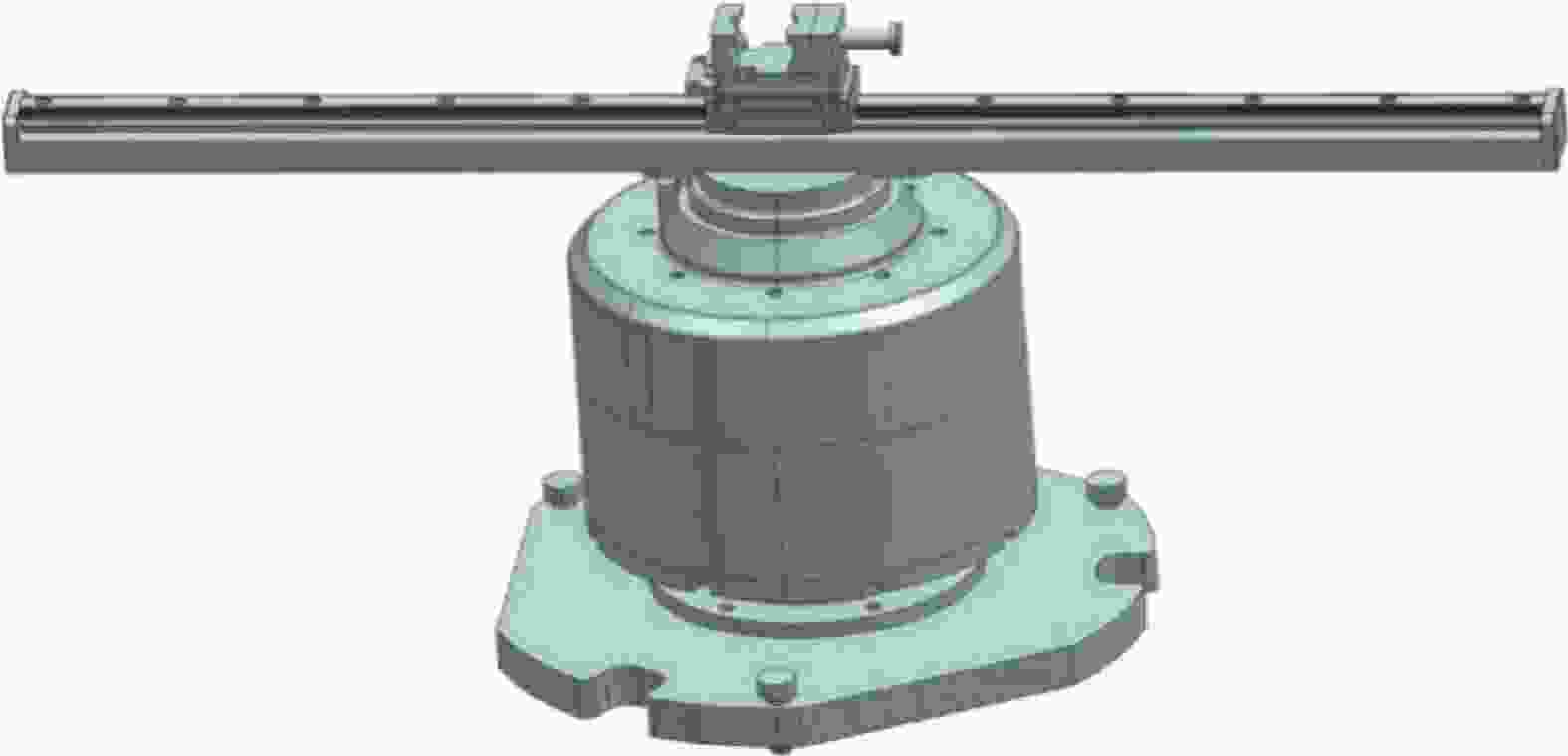
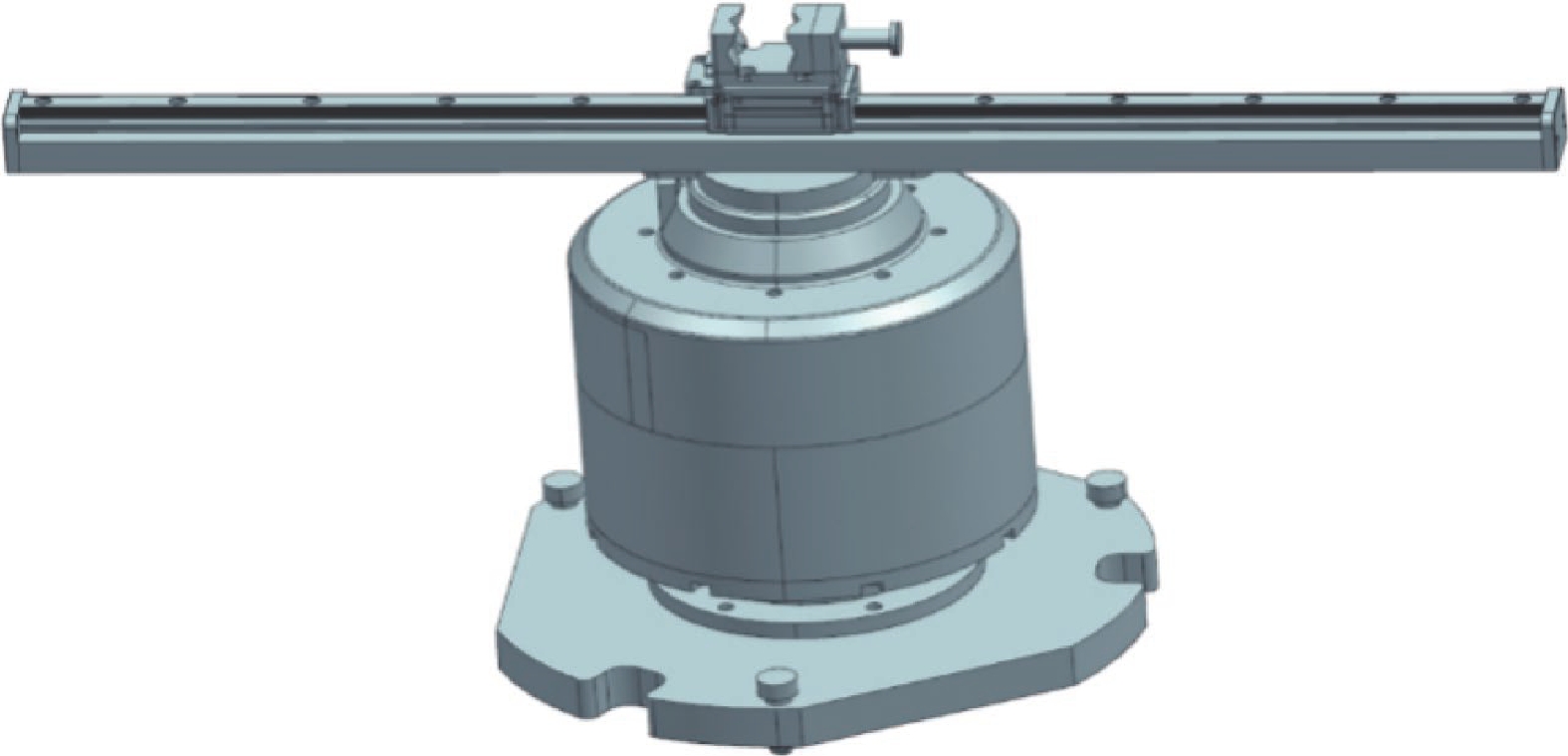
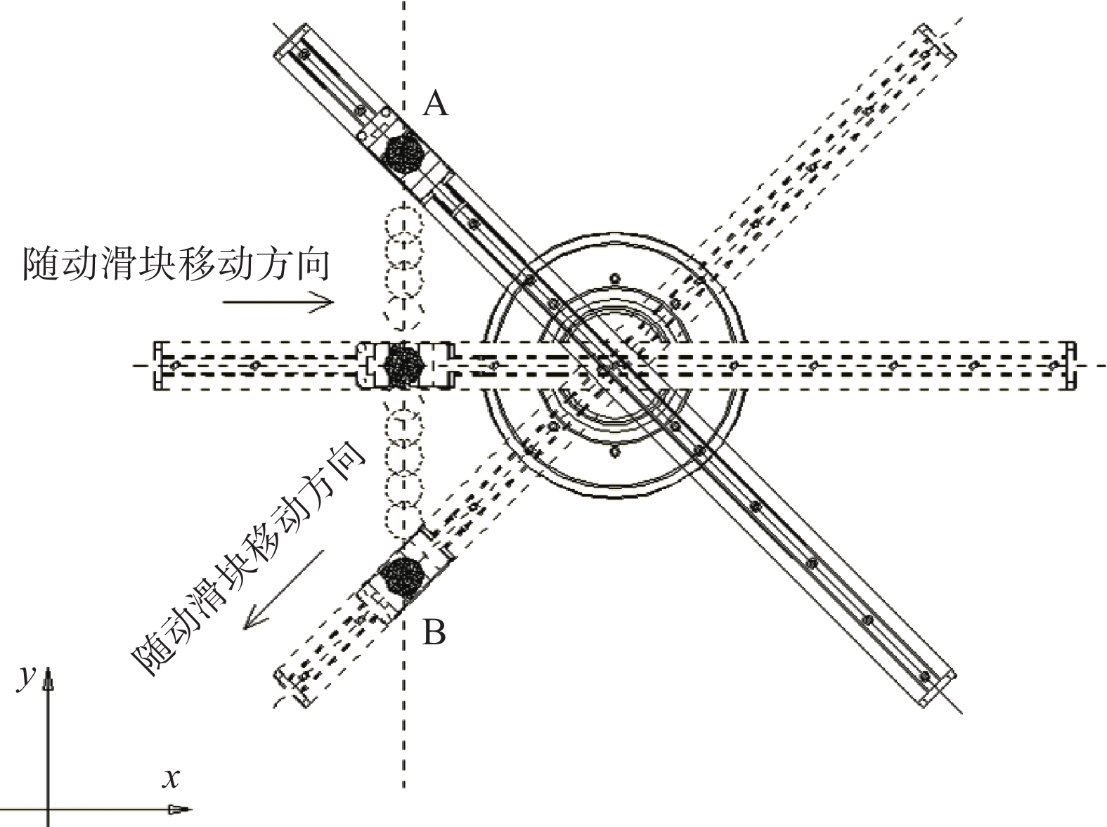
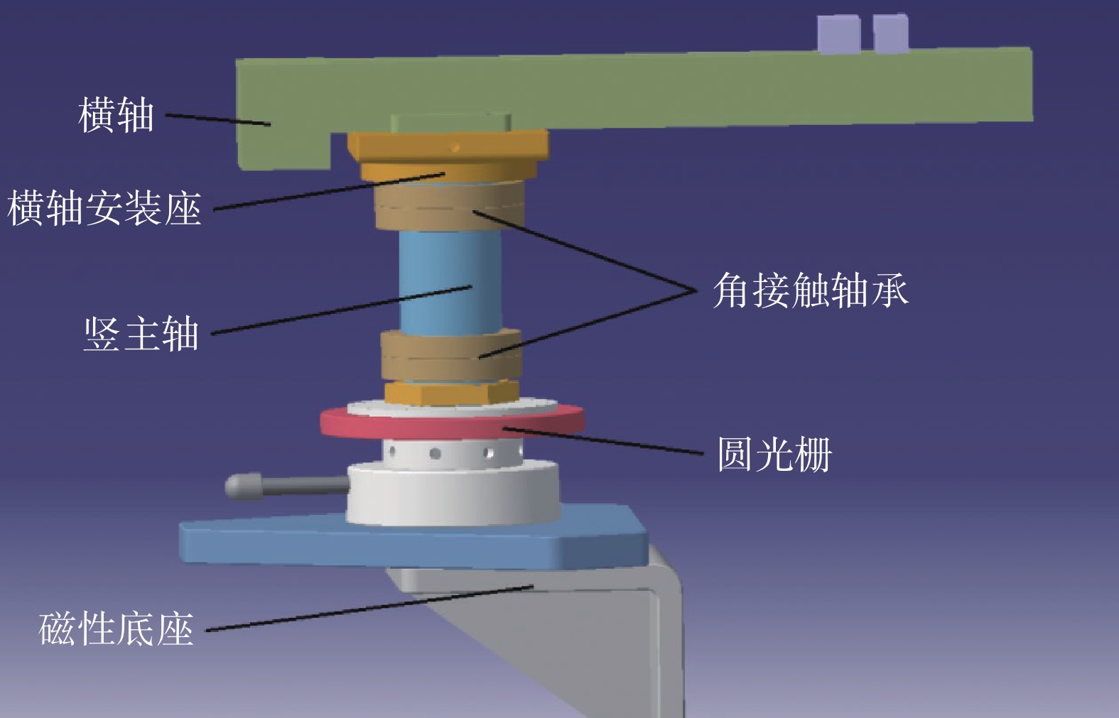
图 3 几何参数随动校准装置效果图
Figure 3. Sketch of geometric parameter follow-up calibration device
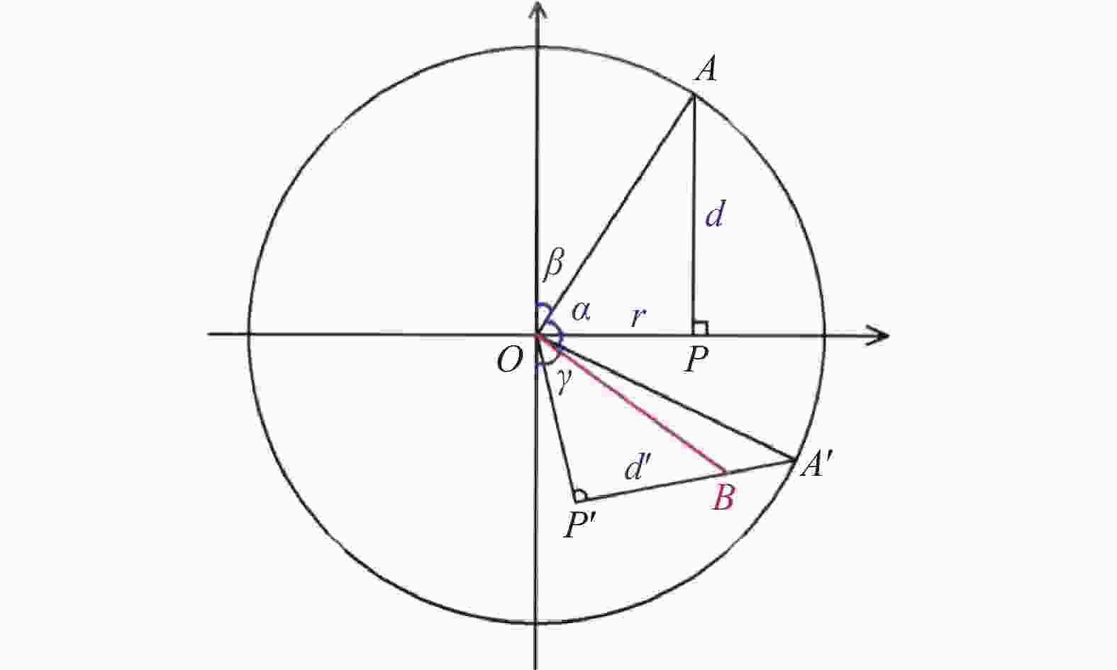
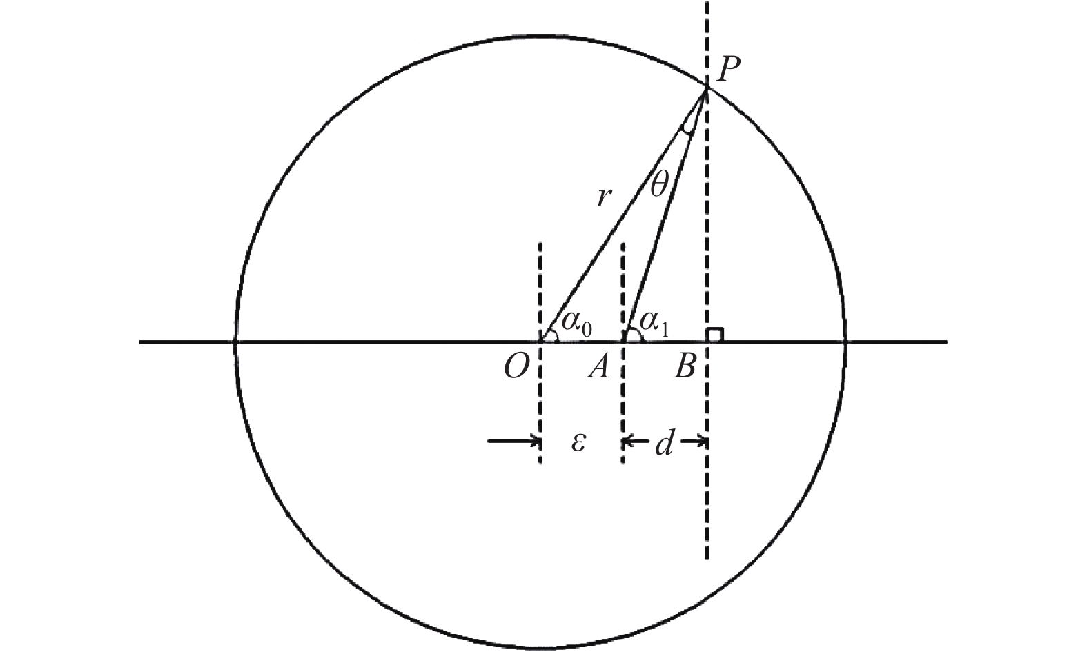
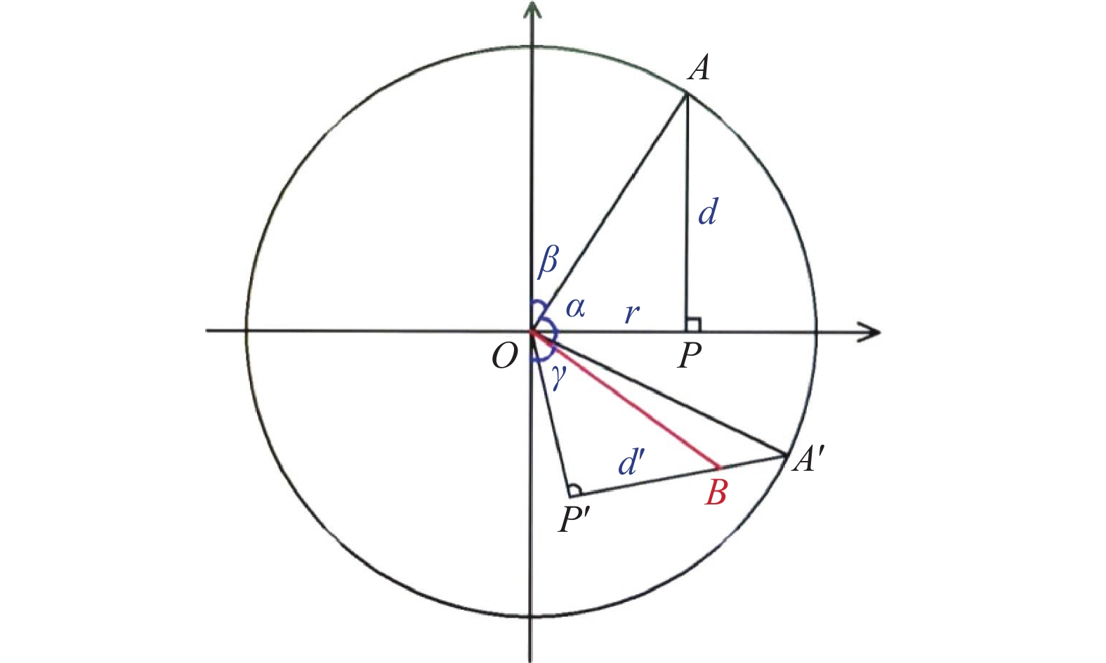
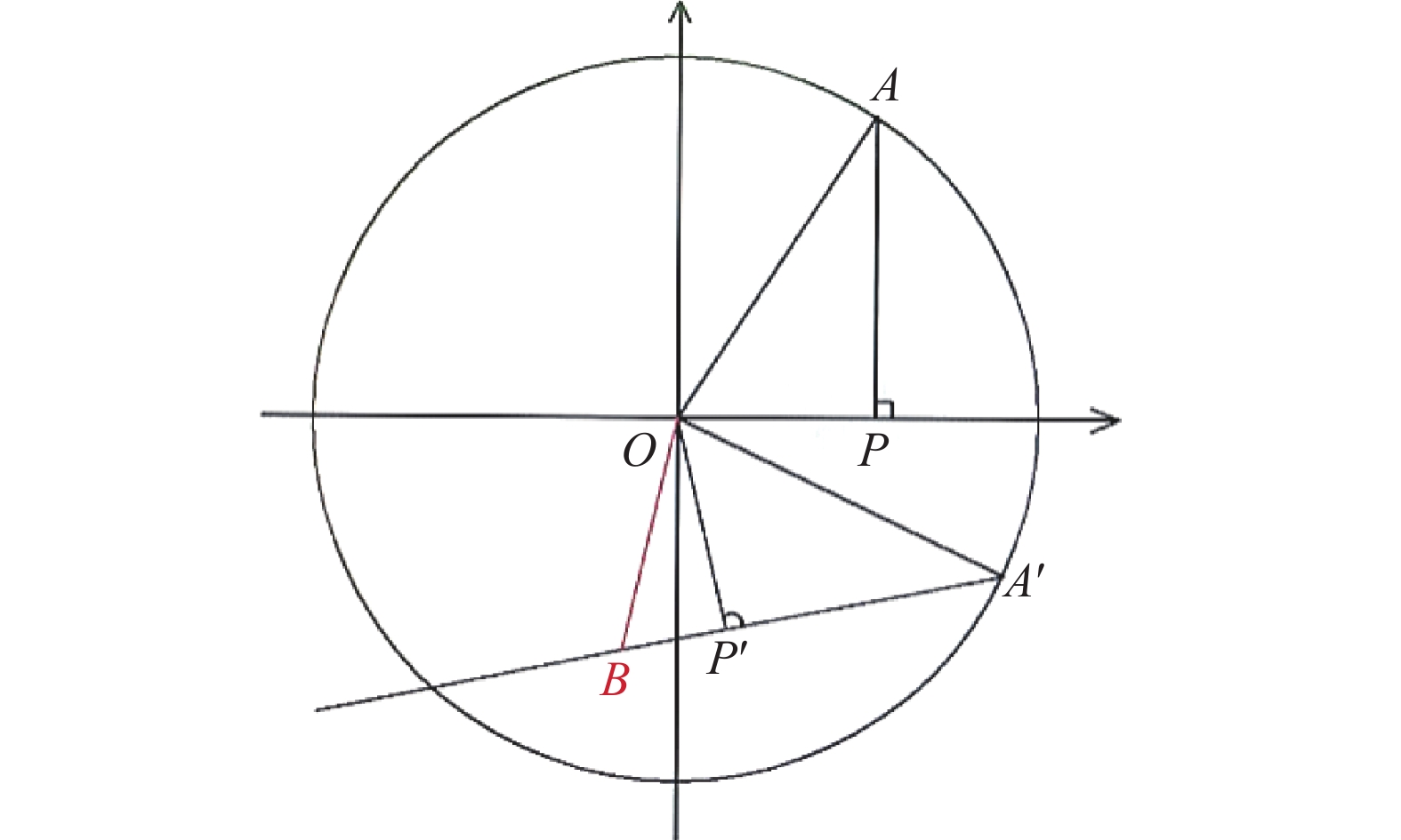
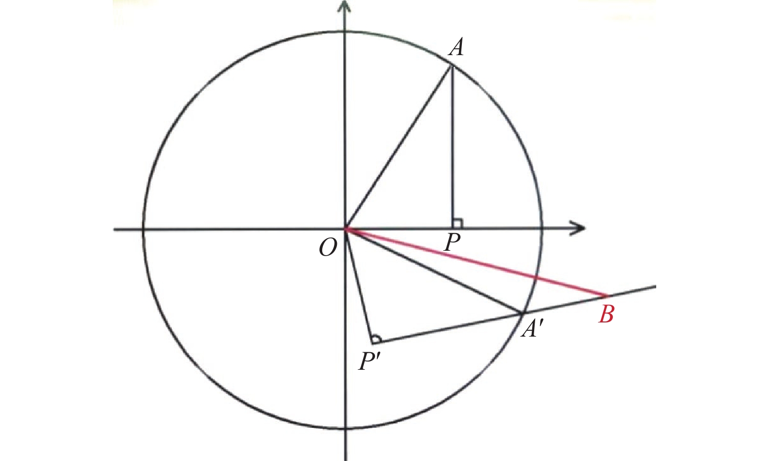
图 14 光栅尺偏心误差导致横轴位置减小模型图
Figure 14. Model diagram of the reduction of the horizontal axis position due to the eccentricity error of the grating ruler
表 1 测长精度验证数据表
Table 1. Length accuracy verification data
序号 圆光栅测
量值/°光栅尺测
量值/mm系统测量
值/mm跟踪仪位
移量/mm系统偏
差/mm0 46.9548 144.313 0.000 0.0000 0.000 1 50.8100 129.944 17.061 17.0661 −0.005 2 54.9846 111.823 37.025 37.0186 0.007 3 59.8579 95.981 55.071 55.0606 0.010 4 63.1061 80.601 70.520 70.5140 0.006 5 67.4881 64.434 86.921 86.9208 0.000 6 71.8353 50.924 100.379 100.3798 −0.001 7 75.6216 43.641 108.013 108.0167 −0.004 8 79.9282 33.491 117.574 117.5813 −0.007 9 85.0266 24.207 126.070 126.0760 −0.006 10 89.3292 16.731 132.354 132.3668 −0.013 11 92.5969 10.144 137.327 137.3402 −0.014 12 96.0236 4.588 141.258 141.2722 −0.014 13 100.6963 0.234 144.075 144.0931 −0.018 14 108.1217 11.058 139.214 139.2329 −0.019 15 115.2887 22.210 137.568 137.5752 −0.007 16 123.8726 31.842 140.474 140.4820 −0.008 17 132.1015 43.053 146.982 146.9858 −0.004 18 140.7998 58.887 159.413 159.4153 −0.002 19 149.2693 71.434 174.094 174.0880 0.006 20 156.1458 85.490 190.347 190.3405 0.007 21 160.7266 97.083 203.803 203.7802 0.023 22 168.3119 112.928 224.796 224.7728 0.023 23 174.9512 126.473 243.495 243.4710 0.024 24 181.8702 142.914 265.281 265.2545 0.027 25 187.4278 159.037 285.529 285.5085 0.021 26 193.0519 176.432 306.960 306.9444 0.015 27 199.4427 190.529 325.431 325.4176 0.013 28 206.6041 209.360 348.307 348.2923 0.015 29 211.3322 227.412 368.456 368.4443 0.012 30 216.3401 242.220 384.988 384.9727 0.015 31 220.7871 256.594 400.375 400.3675 0.008 32 224.9084 271.280 415.534 415.5292 0.004 33 228.2556 281.626 425.913 425.9054 0.008 34 232.8085 287.284 431.091 431.0749 0.016 35 236.7826 274.626 417.541 417.5189 0.022 36 240.7589 264.352 405.951 405.9278 0.023 37 245.8744 256.194 395.477 395.4557 0.021 38 250.4876 243.629 380.317 380.2947 0.022 39 255.2054 231.569 365.124 365.1033 0.021 40 260.0569 214.757 344.763 344.7533 0.010 41 266.2962 193.851 318.854 318.8456 0.008 42 271.4724 176.559 297.203 297.2132 −0.011 43 276.6285 157.907 274.322 274.3290 −0.007 44 281.7923 138.656 251.197 251.2043 −0.007 45 287.6925 125.488 232.984 232.9916 −0.007 46 293.2131 108.711 212.803 212.8123 −0.009 47 299.5474 91.664 192.758 192.7714 −0.013 48 306.0202 74.698 174.678 174.6823 −0.004 49 312.1679 60.203 161.001 161.0014 −0.001 50 318.5758 49.953 151.449 151.4476 0.001 51 323.1455 32.308 144.540 144.5330 0.007 52 328.0894 22.653 141.796 141.7931 0.003 53 333.9613 14.130 140.938 140.9223 0.016 54 339.8689 4.382 142.775 142.7675 0.007 55 345.6752 3.946 142.565 142.5573 0.008 56 351.9912 21.755 133.114 133.1075 0.006 57 357.5139 40.040 122.206 122.2082 −0.002 58 1.5634 58.771 111.278 111.2839 −0.006 59 5.2059 78.499 100.476 100.4776 −0.001 60 8.8706 103.403 89.630 89.6556 −0.025 61 12.0322 120.806 82.672 82.6695 0.002 62 15.1457 146.050 79.586 79.6000 −0.014 63 17.8558 171.188 83.400 83.3917 0.008 64 20.3316 191.622 89.983 89.9683 0.015  下载: 导出CSV
-
[1] 阮大文, 茅健, 刘钢, 等. 双五轴数控铣削机床旋转轴误差辨识方法[J]. 中国机械工程, 2020, 31(13): 1548-1554. [2] 马国艳. 数控机床回转轴应用技术[J]. 世界制造技术与装备市场, 2020(5): 84-85. doi: 10.3969/j.issn.1015-4809.2020.05.027 [3] 苟铖, 彭希锋, 张强. 几何量综合自动检定装置设计[J]. 计量技术, 2018(12): 54-57. [4] 徐永, 孙安斌, 曹铁泽, 等. RCS测试系统几何量参数综合校准技术研究[J]. 宇航计测技术, 2015, 35(5): 70-74. doi: 10.3969/j.issn.1000-7202.2015.05.019 [5] 厉志飞, 陈刚, 赵建峰, 等. 基于激光位移传感器与标准样板的机器人几何参数标定[J]. 计量技术, 2019(9): 17-21. [6] 葛敏雪. 高分辨率锥束CT系统几何校准方法研究[D]. 重庆: 重庆大学, 2018. [7] 张辰, 吴丕杰. 水浸超声C扫描检测系统的机械精度对检测结果的影响[J]. 中国钛业, 2017(1): 36-39. [8] 董欣媛, 孙双花, 崔京远, 等. 基于正交双轴激光干涉仪的二维光栅校准系统误差分析[J]. 计量学报, 2019, 40(S1): 36-41. [9] 常莹. RVDT角位移传感器校准技术研究[J]. 宇航计测技术, 2019, 39(S1): 61-66. [10] 林云川, 程志远. 数控机床在线测量系统校准技术研究[J]. 计测技术, 2020, 40(4): 19-22. [11] 李新, 茅晨, 马涛, 等. 利用Leica激光跟踪仪对工业机器人现场标定的方法[J]. 计量技术, 2019(11): 64-68. [12] 焦扬, 黄明, 刘品宽, 等. 双角度编码器超精密转台测角误差校准[J]. 光学精密工程, 2019, 27(10): 2180-2191. [13] 魏枫, 王欢, 宋薇. 基于二维转台与空间方位角标定装置的电磁轨道发射轴线标定与校准装置设计[J]. 科技创新与应用, 2019(3): 6-10. [14] 黄建明, 张明达. 角位移传感器自动校准系统[J]. 计量技术, 2017(4): 40-43. [15] 王民越. 数控机床在线测量系统校准方法的研究[D]. 大连: 大连理工大学, 2018. -


 点击查看大图
图(16) / 表(1)
计量
- 文章访问数: 237
- HTML全文浏览量: 98
- PDF下载量: 27
- 被引次数: 0

