 作者投稿
作者投稿 专家审稿
专家审稿 编辑办公
编辑办公

Methodology and Technology for Ultra-Precise Rotary Axes Motion Error Measurement
-
摘要: 高超精密回转轴在高端装备中应用广泛,而回转运动误差会影响这些设备的精度。第一类传统的回转运动误差测量技术往往需要一个高精度标准器件作为参考,由于标准器形状误差的限制,其不可避免地降低了回转运动误差测量精度,而误差分离技术又很繁琐且费时。第二类基于光学方法回转运动误差测量技术则无法获得高测量精度并且难以获得轴向运动误差。分析了超高精度非球面测量仪器中回转运动误差的影响,并概述了现有两类回转运动误差测量方法。最后分析了所提出的基于复合激光靶标的回转运动误差测量方法,该方法可以测量转轴在运动过程中五个自由度误差,具体包括轴向、径向和角度误差。在这种方法中,建造了一个包含激光点光源和激光准直光束的复合激光靶标,并将其安装在转轴上作为参考基准,其用于标记转轴在回转过程中的位置,通过测量复合激光靶标的位置和角度来获得转轴的姿态。差动共焦显微测量技术被用于测量激光点光源的轴向位置,以获得转轴的轴向误差;传统显微光路用于测量激光点光源的径向位置,以获得转轴的径向误差;准直测量光路用于获得激光准直光束的角度,以获得转轴的角度误差。对轴向和径向误差的分辨力分别为4 nm和2 nm,对角度误差的分辨力为0.2 μrad。此外,该方法还在空气转轴上进行了测试,并证明了在使用该方法获得转轴运动误差的可行性。综上,该方法通过光学参考装置替代传统标准器件来获得转轴误差,而无需额外的误差分离过程。在超高精度测量设备中,该方法有利于实现回转运动误差的实时监测,有望在超精密加工和测量等领域进行更多实际应用。Abstract: Ultra-precise rotary axes are extensively utilized in advanced equipment, and their motion errors can significantly impact the accuracy of these devices. Traditional measurement techniques for rotary axes errors typically involve high-precision standard devices as references, but these can inadvertently reduce measurement accuracy due to inherent shape errors. Furthermore, error separation techniques are both cumbersome and time-consuming. Optical-based measurement methods, though useful, often fail to achieve high accuracy, especially in measuring axial motion errors. This paper addresses the impact of rotary axes motion errors in ultra-high precision aspheric measuring instruments and reviews two existing measurement methods. It introduces a novel measurement approach based on a composite laser target capable of assessing five degrees of freedom in motion errors, including axial, radial, and angular errors. This method employs a composite laser target equipped with a laser point light source and a collimated laser beam, affixed to the rotary axes as a reference datum. The method's efficacy is demonstrated in accurately determining the axes' position and orientation by measuring the target's position and angle. The differential confocal microscopy technique is applied to ascertain the axial position of the laser point source, thereby determining the axes' axial error, while a traditional microscope optical path measures the radial position for radial error. Collimation measurement optical path is used to evaluate the laser collimation beam's angle for angular error assessment. The method exhibits resolutions of 4 nm for axial, 2 nm for radial, and 0.2 μrad for angular errors. Moreover, the feasibility of this method in measuring rotary axes motion errors is validated through tests on an air spindle. Overall, this approach replaces traditional standard devices with an optical reference device, eliminating the need for additional error separation processes and facilitating real-time monitoring of rotary axes motion errors in ultra-high-precision measuring equipment.
-
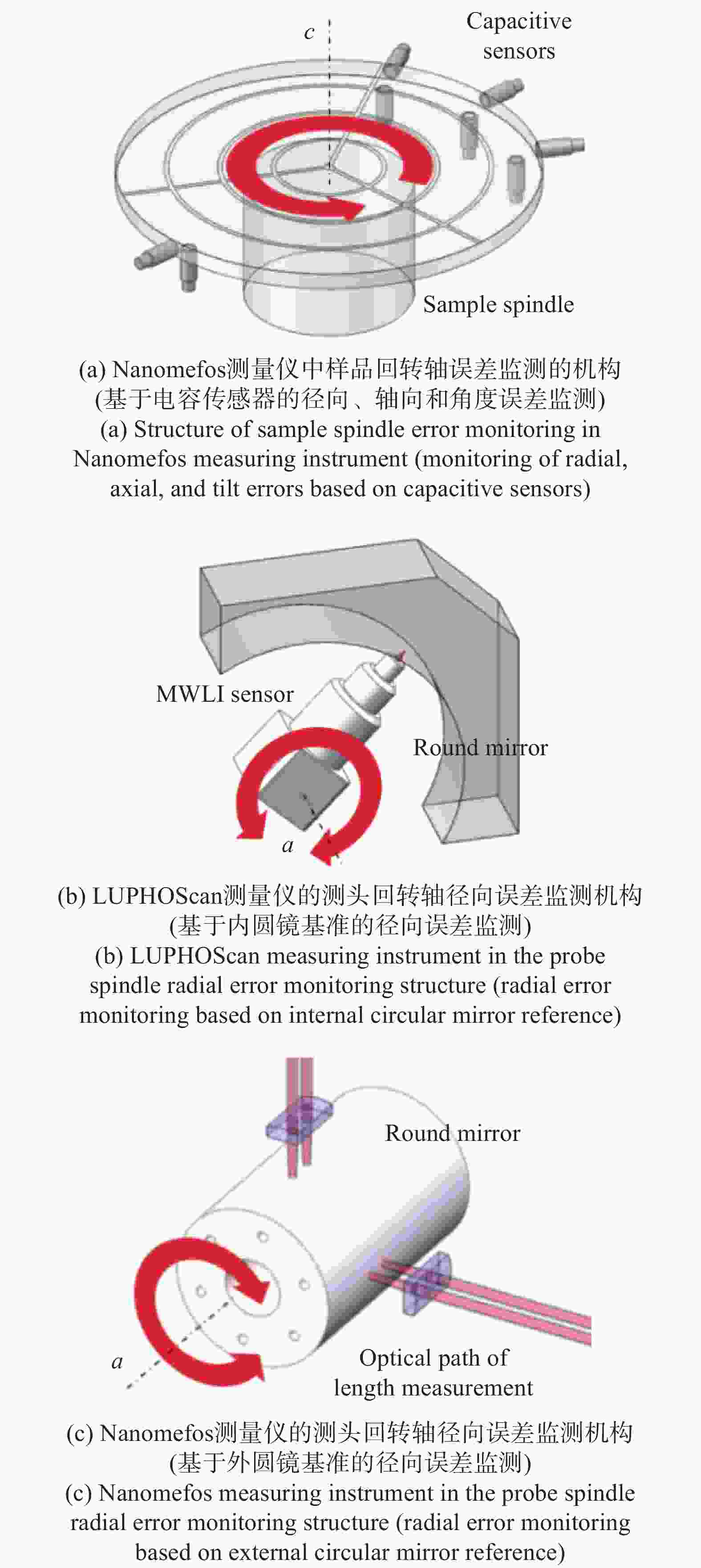
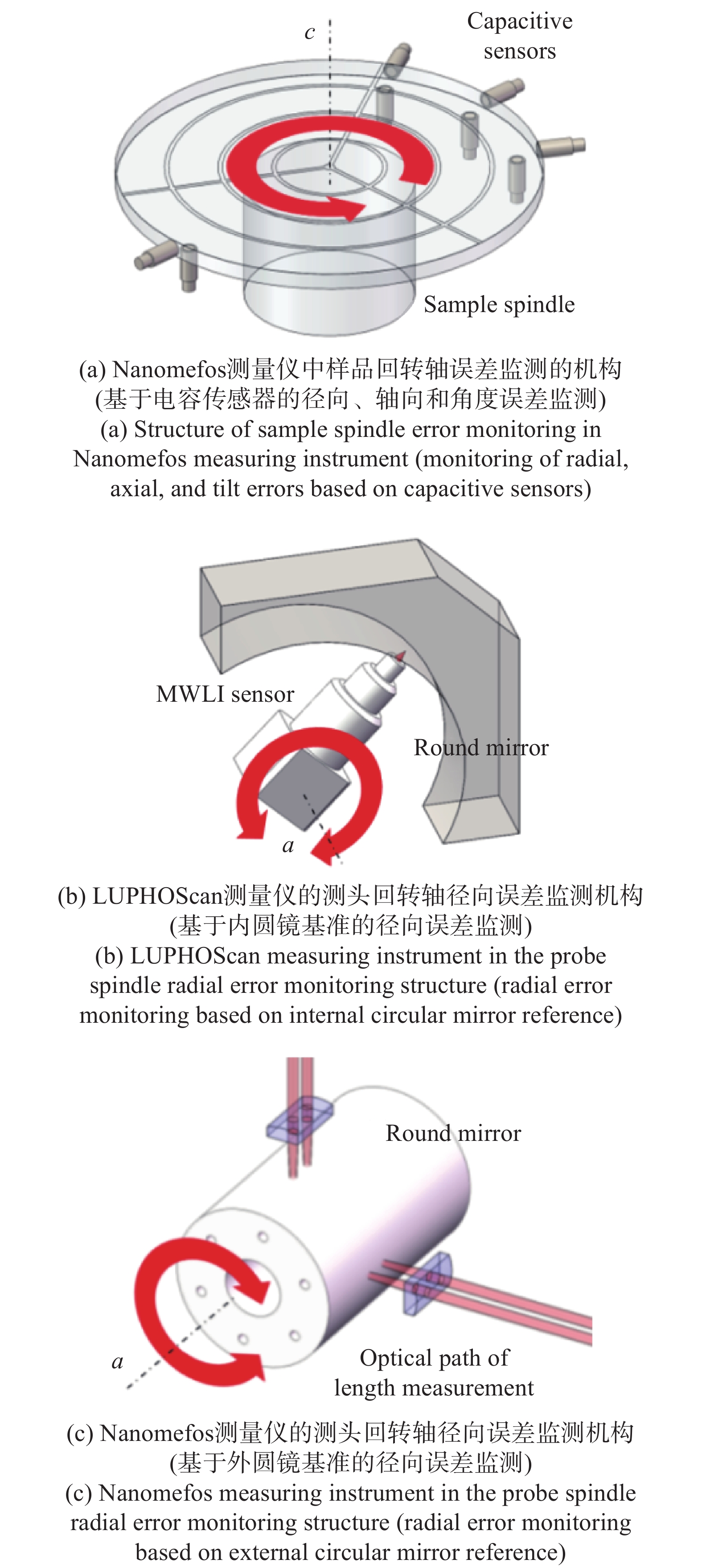
图 3 非球面测量仪器的回转轴误差监测方法
Figure 3. Spindle error monitoring method for aspheric measuring instruments

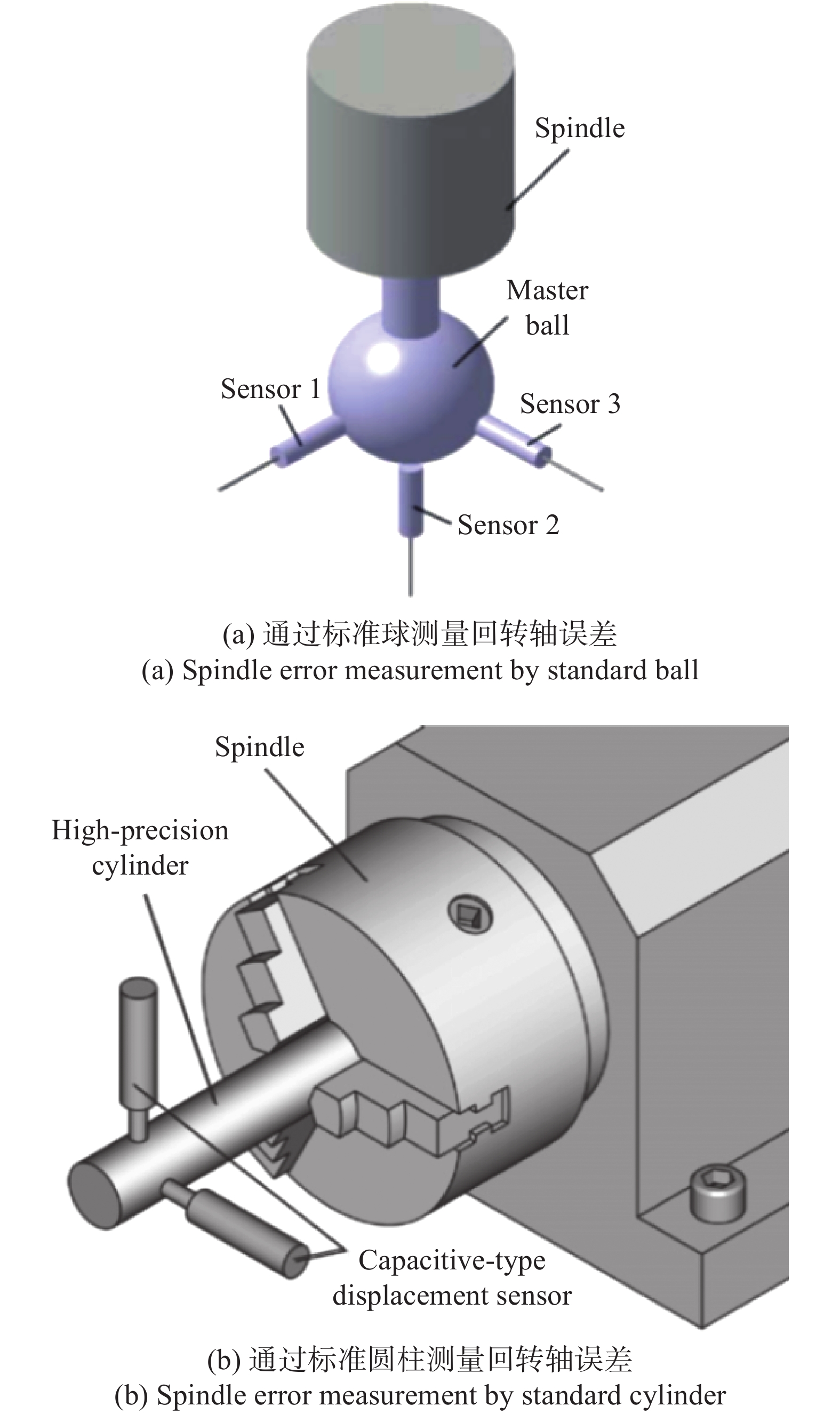
图 4 基于标准器件的回转轴误差测量原理图
Figure 4. Principle diagram of spindle error measurement based on standard devices
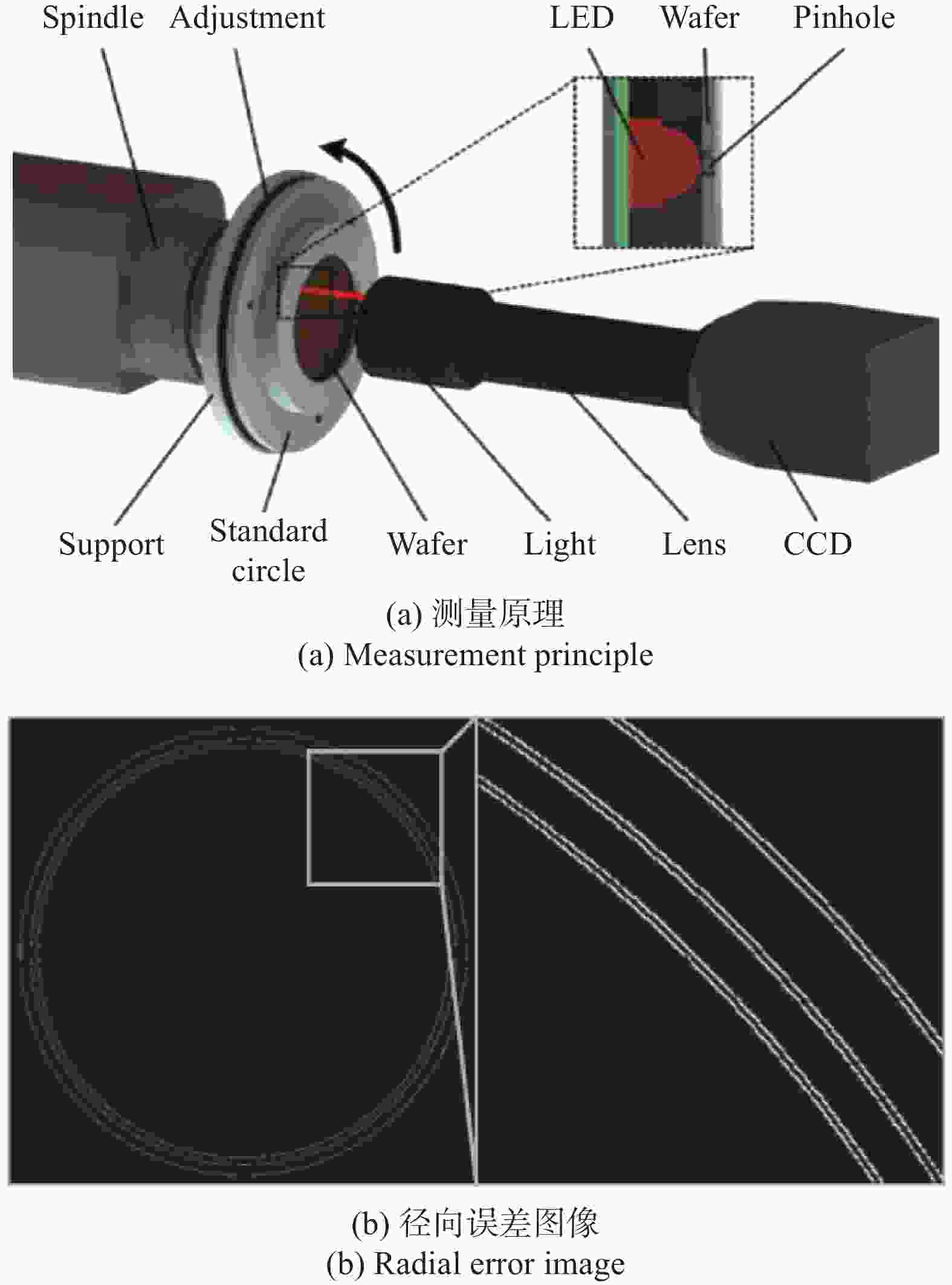
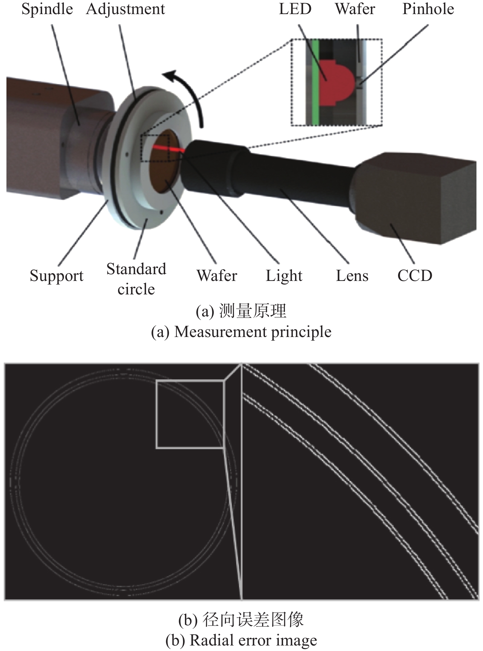
图 5 基于CCD视觉系统的回转轴径向运动误差测量
Figure 5. Measurement of spindle radial motion error based on CCD vision system
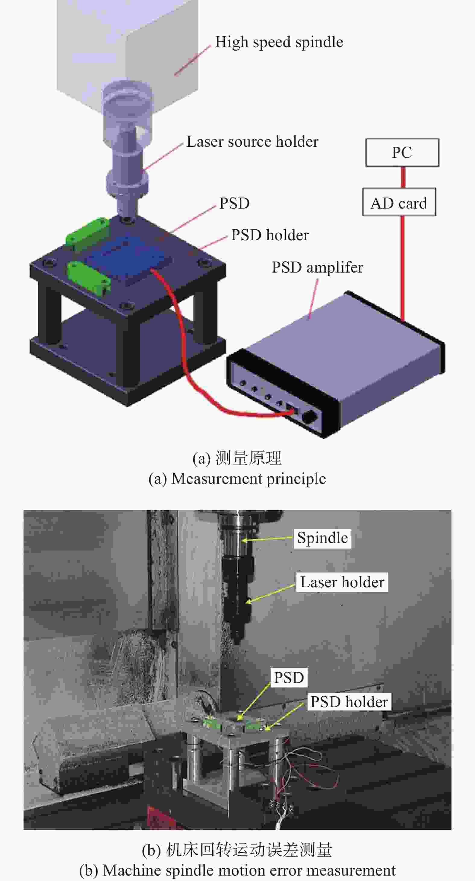
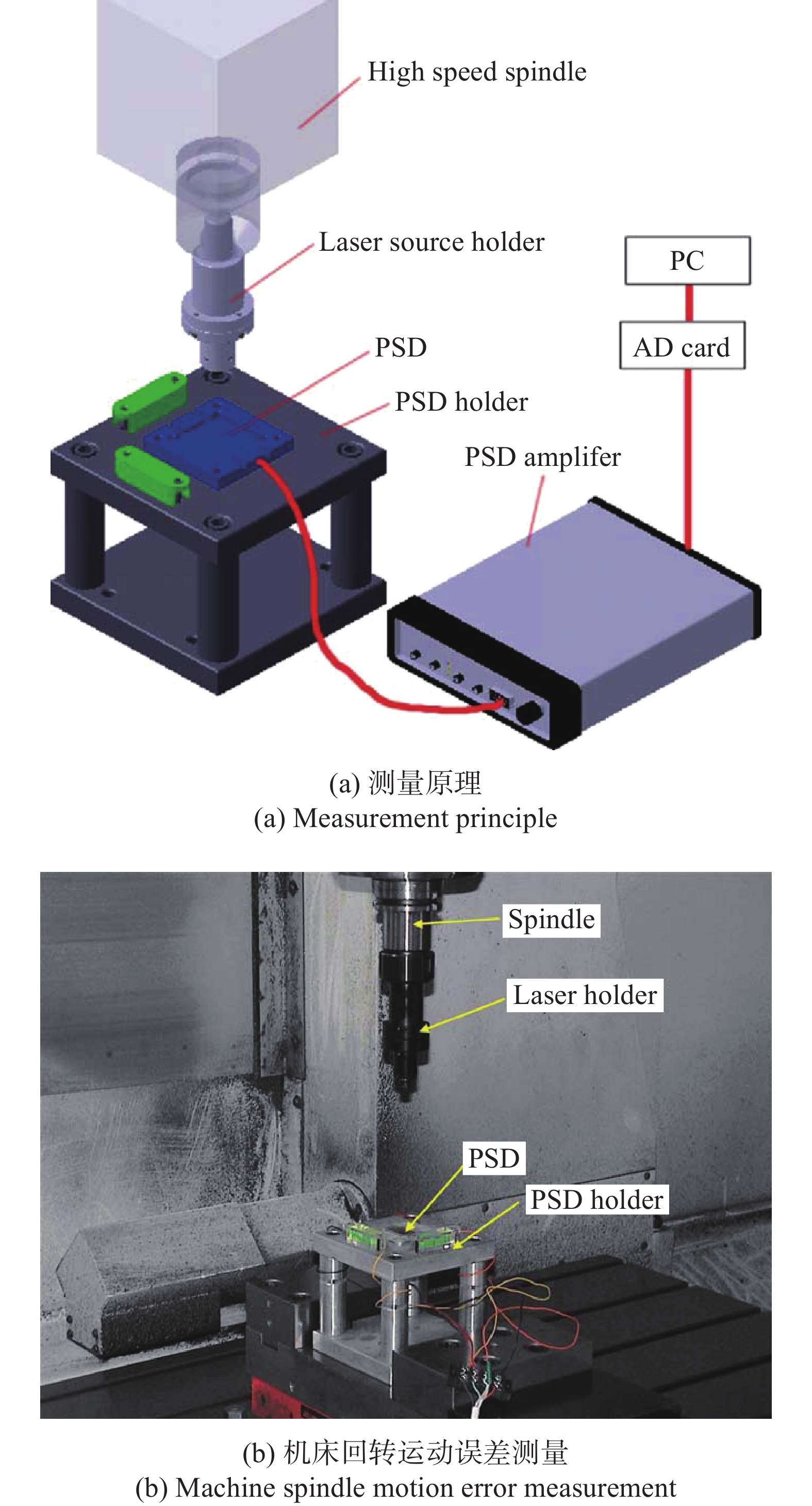
图 6 基于PSD的回转轴径向运动误差测量
Figure 6. Measurement of spindle radial motion error based on PSD
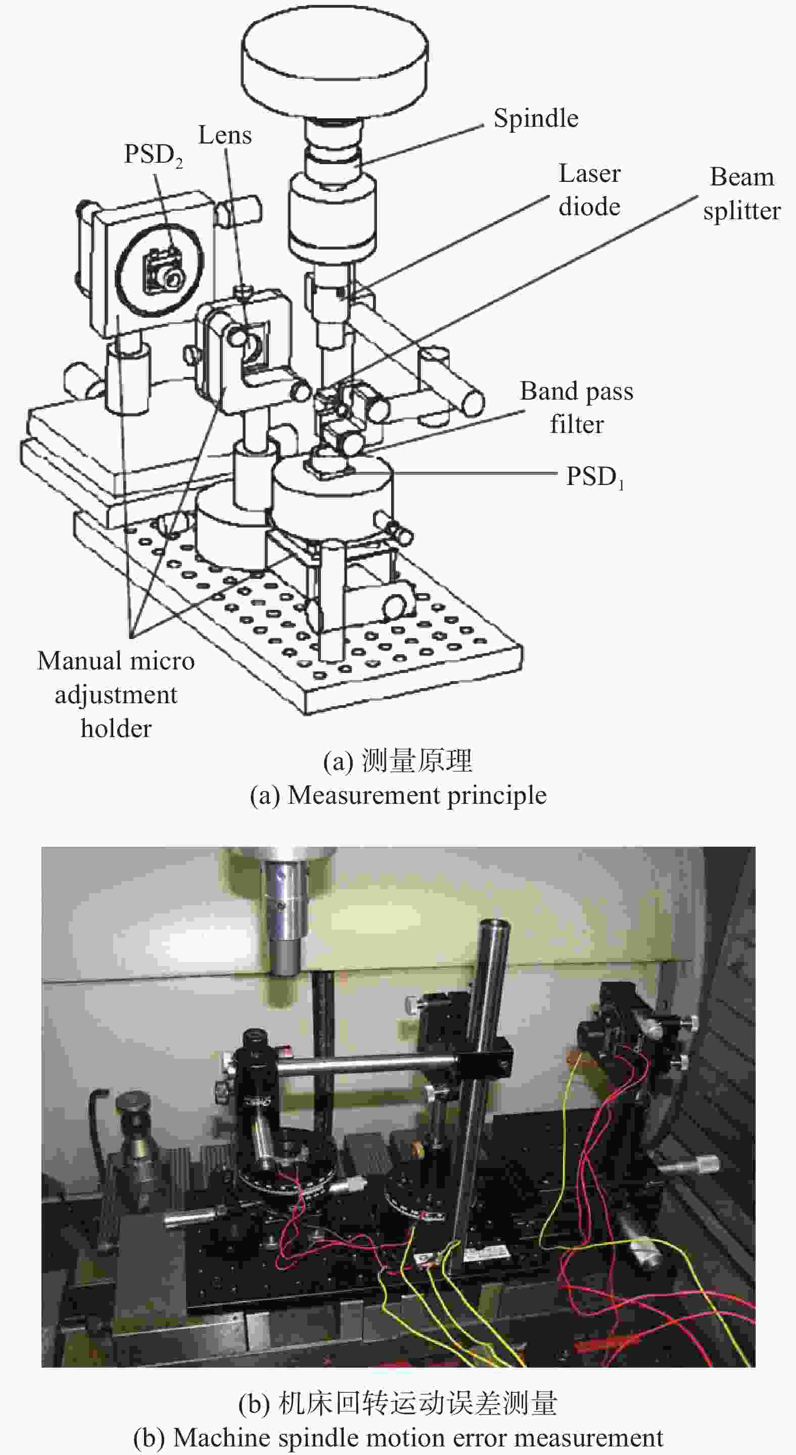
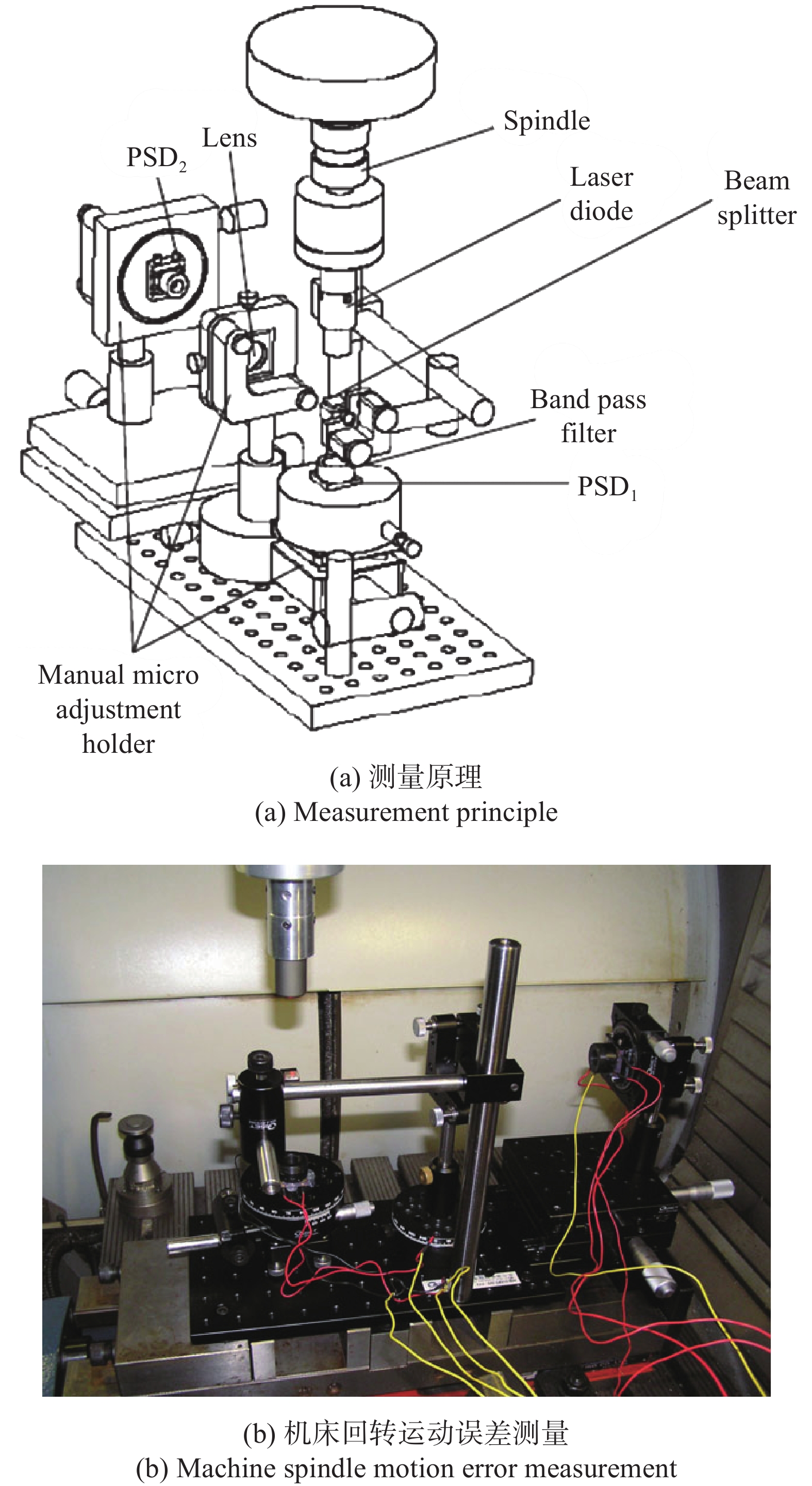
图 7 基于多个PSD测量回转轴径向运动误差和角度误差
Figure 7. Measurement of spindle radial motion error and tilt error based on multiple PSD
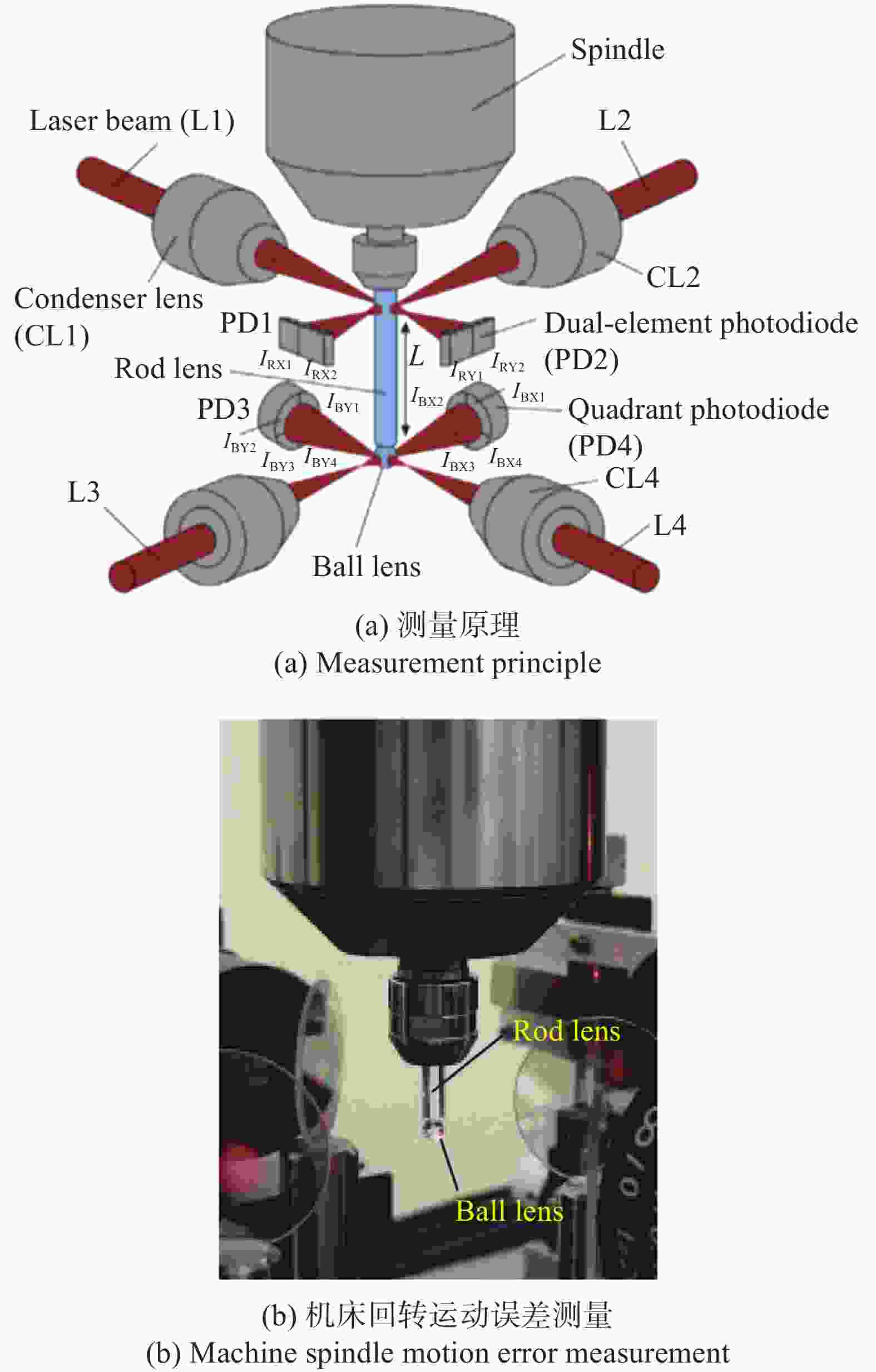
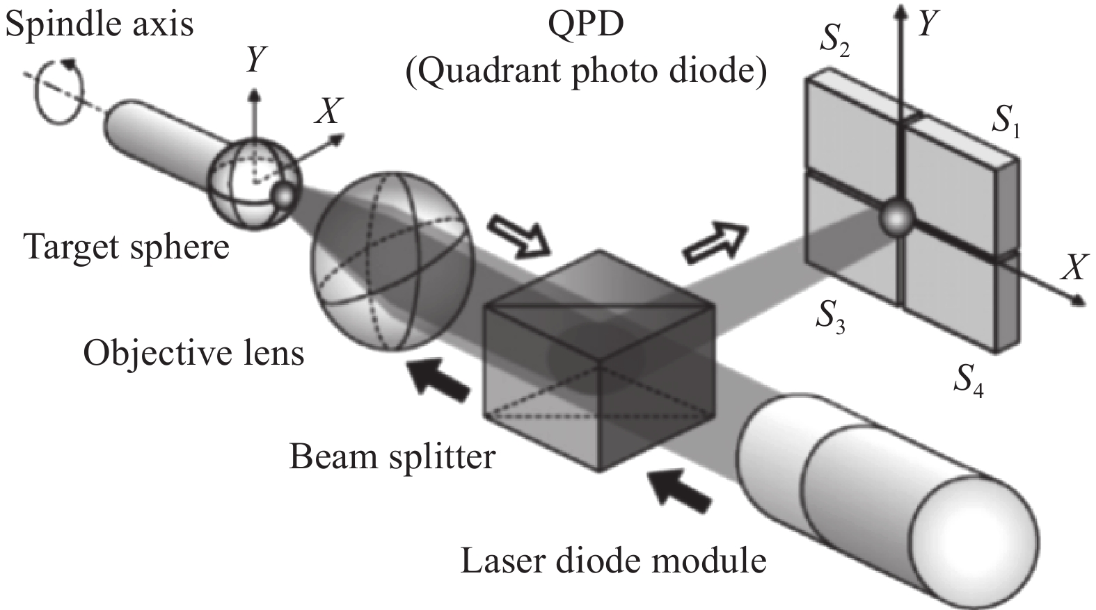
图 9 基于柱透镜和球透镜的回转轴误差测量方法
Figure 9. Spindle error measurement method based on column lens and ball lens

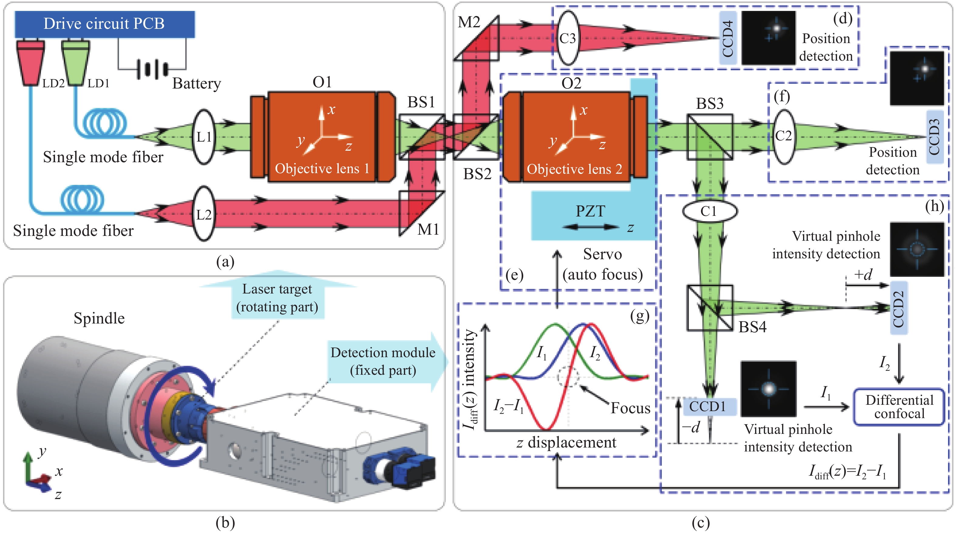
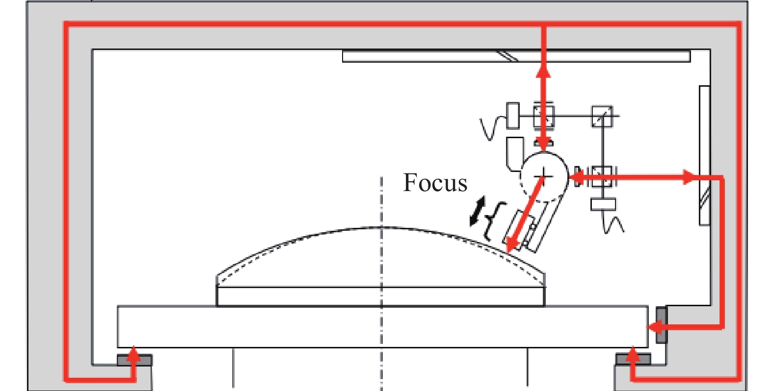
图 10 基于复合激光靶标的回转轴误差监测方法示意图(a 复合激光靶标部分;b 复合激光靶标和激光探测模块的安装图;c 激光检测模块部分;d 准直检测部分;e 自动跟踪聚焦部分;f 激光聚焦位置检测部分;g 差动共焦轴向响应曲线;h 激光差动共焦检测部分)
Figure 10. Schematic diagram of the spindle error monitoring method based onthe composite laser target (a Composite laser target part; b Installation diagram of the composite laser target and laser detection module; c Laser detection module part; d Collimation detection part; e Auto-tracking focusing part; f Laser focus position detection part; g Differential confocal axial response curve; h Laser differential confocal detection part)

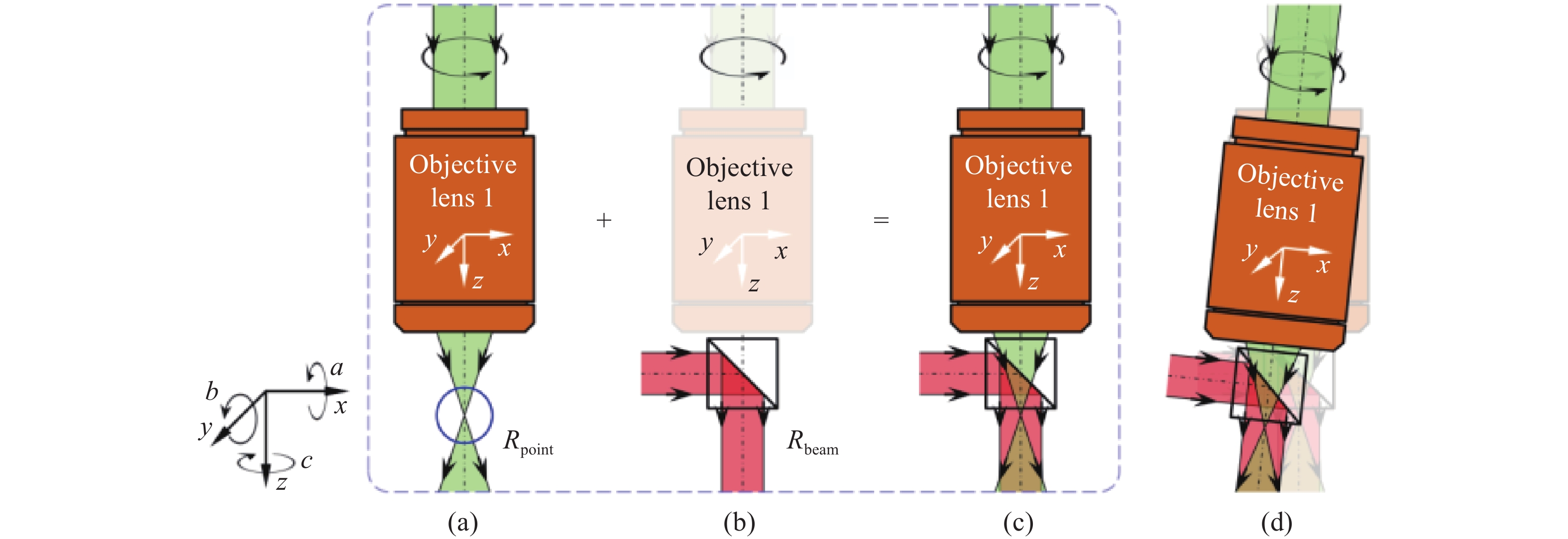
图 11 用于标记回转轴误差的复合激光靶标原理图(a 激光焦点Rpoint示意图;b 准直光束Rbeam示意图;c激光焦点Rpoint和准直光束Rbeam复合示意图;d 回转轴误差导致激光焦点Rpoint和准直光束Rbeam发生变化示意图)
Figure 11. Principle of the composite laser target used to mark spindle error (a Laser focal point Rpoint; b collimated beam Rbeam; c Composite laser focus Rpoint and collimated beam Rbeam; d Spindle error causes the laser focus Rpoint and collimated beam Rbeam to change)
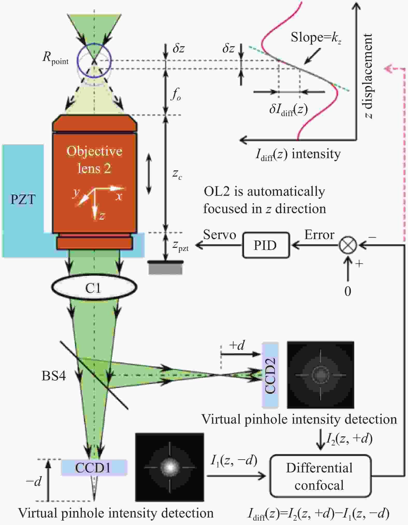
图 12 差动共焦跟踪测量轴向位移的原理
Figure 12. Principle of differential confocal tracking measurement of axial displacement
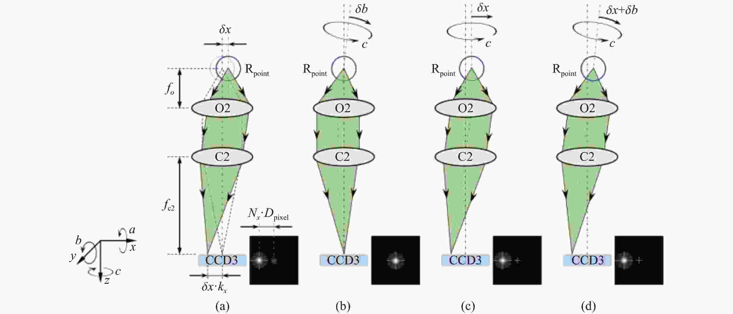
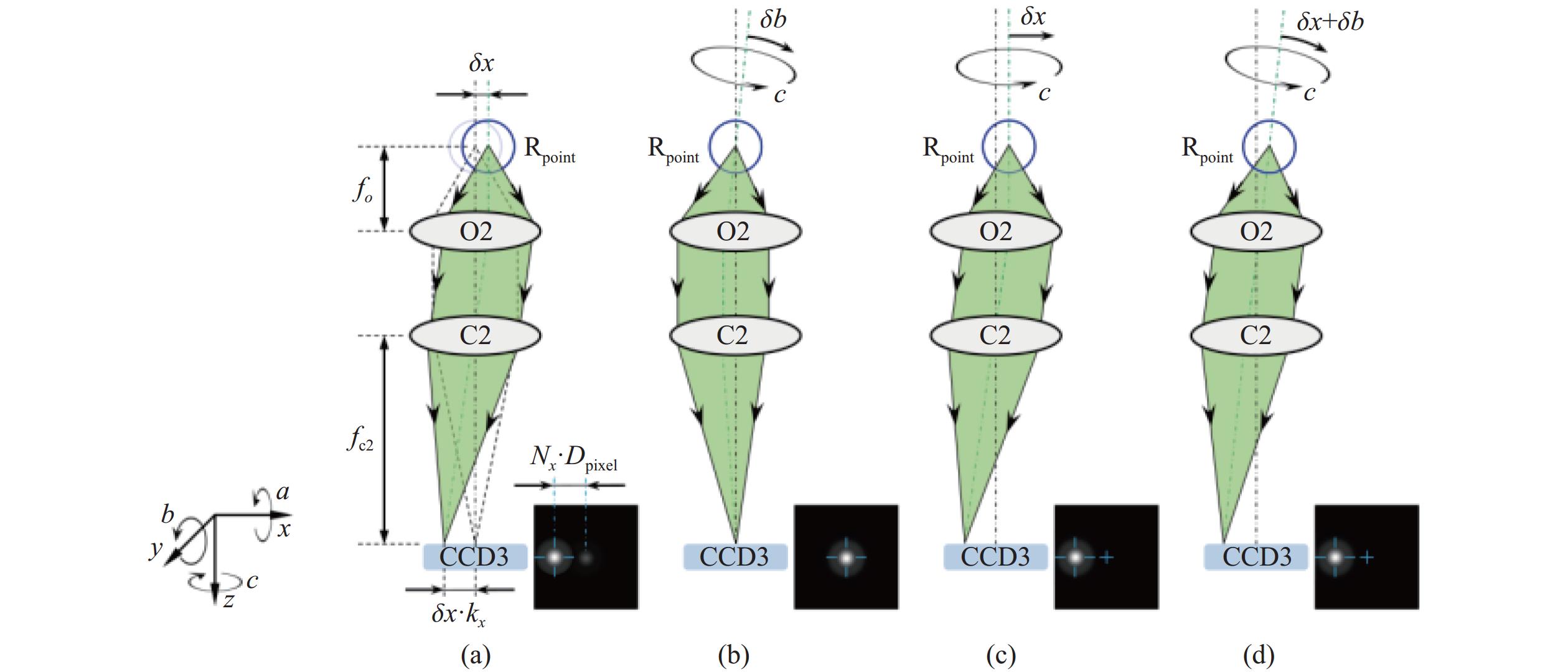
图 13 回转轴径向误差测量部分(a 激光焦点Rpoint的径向位置与CCD上光斑位置关系;b 只有角度误差δb影响下的CCD光斑位置示意图;c 只有径向误差δx影响下的CCD光斑位置示意图;d 径向误差δx和角度误差δb共同影响下的CCD光斑位置示意图)
Figure 13. Spindle radial error measurement section (a Radial position of the laser focus Rpoint in relation to the position of the spot on the CCD; b Schematic diagram of CCD spot position under the influence of only tilt error δb; c Schematic diagram of CCD spot position under the influence of only radial error δx; d Schematic diagram of CCD spot position under the joint influence of radial error δx and tilt error δb)
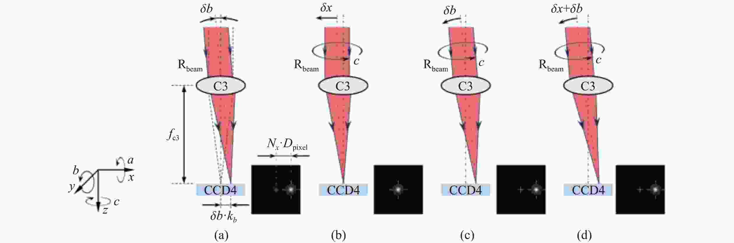
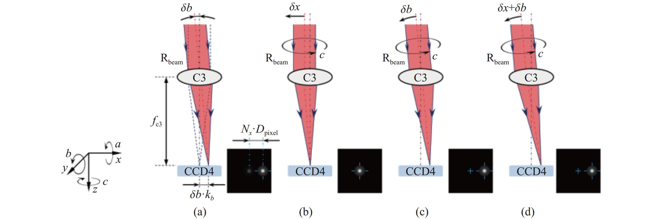
图 14 回转轴倾角误差测量部分(a 准直光束Rbeam的角度与CCD上光斑位置关系;b 只有径向误差δx影响下的CCD光斑位置示意图;c 只有角度误差δb影响下的CCD光斑位置示意图; d 径向误差δx和角度误差δb共同影响下的CCD光斑位置示意图)
Figure 14. Spindle tilt error measurement section (a The angle of the collimated beam Rbeam in relation to the position of the spot on the CCD; b Schematic diagram of CCD spot position under the influence of only tilt error δb; c Schematic diagram of CCD spot position under the influence of only radial error δx; d Schematic diagram of CCD spot position under the joint influence of radial error δx and tilt error δb)
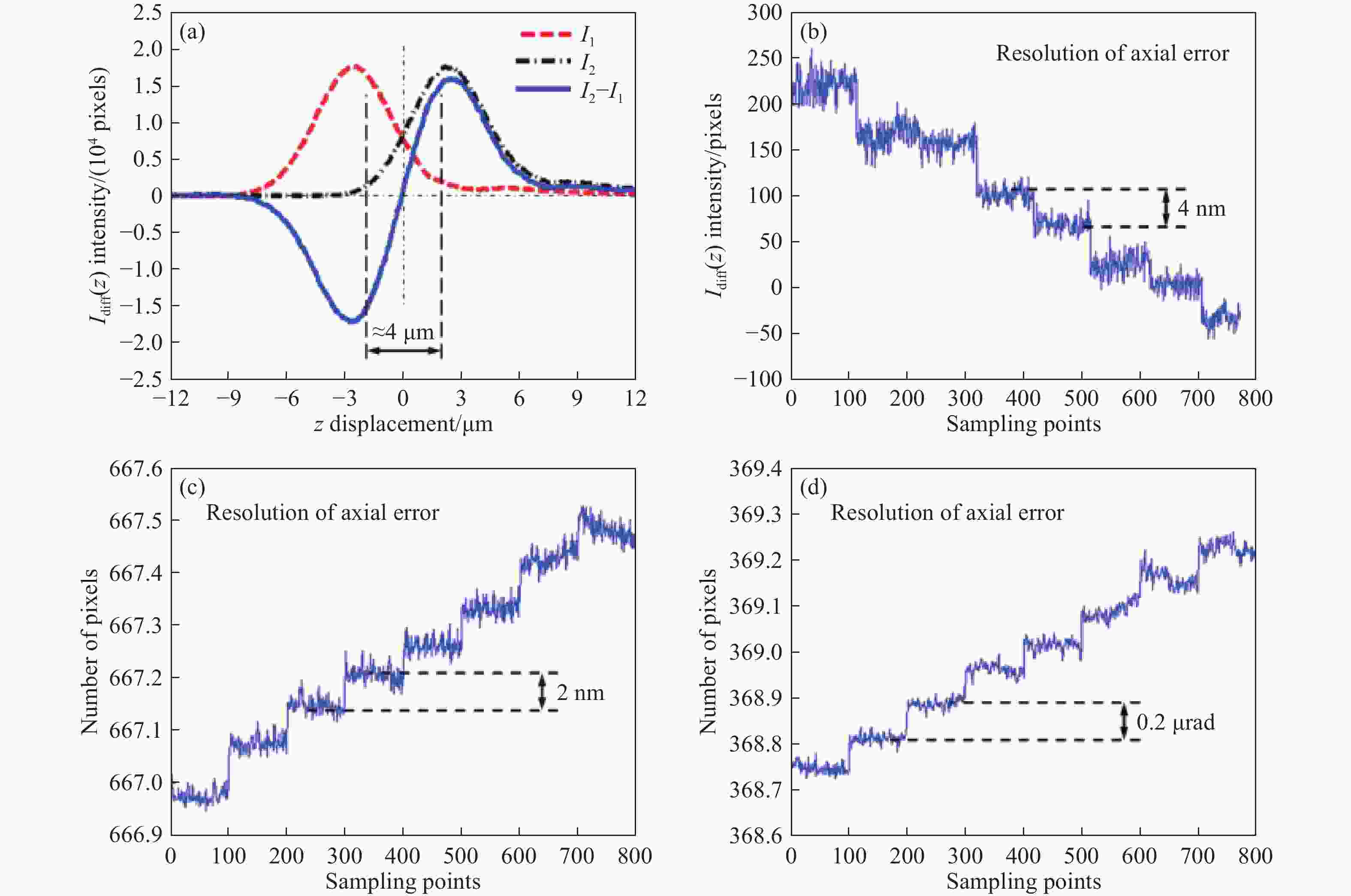
图 15 测试结果(a 激光点光源差动共焦曲线;b 轴向分辨力;c 径向分辨力;d 角度分辨力)
Figure 15. Test results (a Laser point source differential confocal curve; b Axial resolution; c Radial resolution; d Tilt resolution)

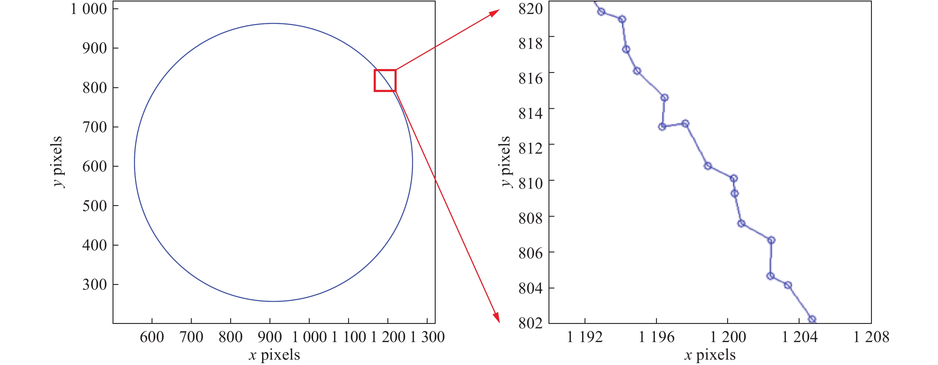
图 17 径向误差测试点轨迹(a 圆形轨迹;b 圆形轨迹的局部放大显示)
Figure 17. Spot trajectories for the radial error test (a Circular trajectory; b Partial enlargement of the trajectory)
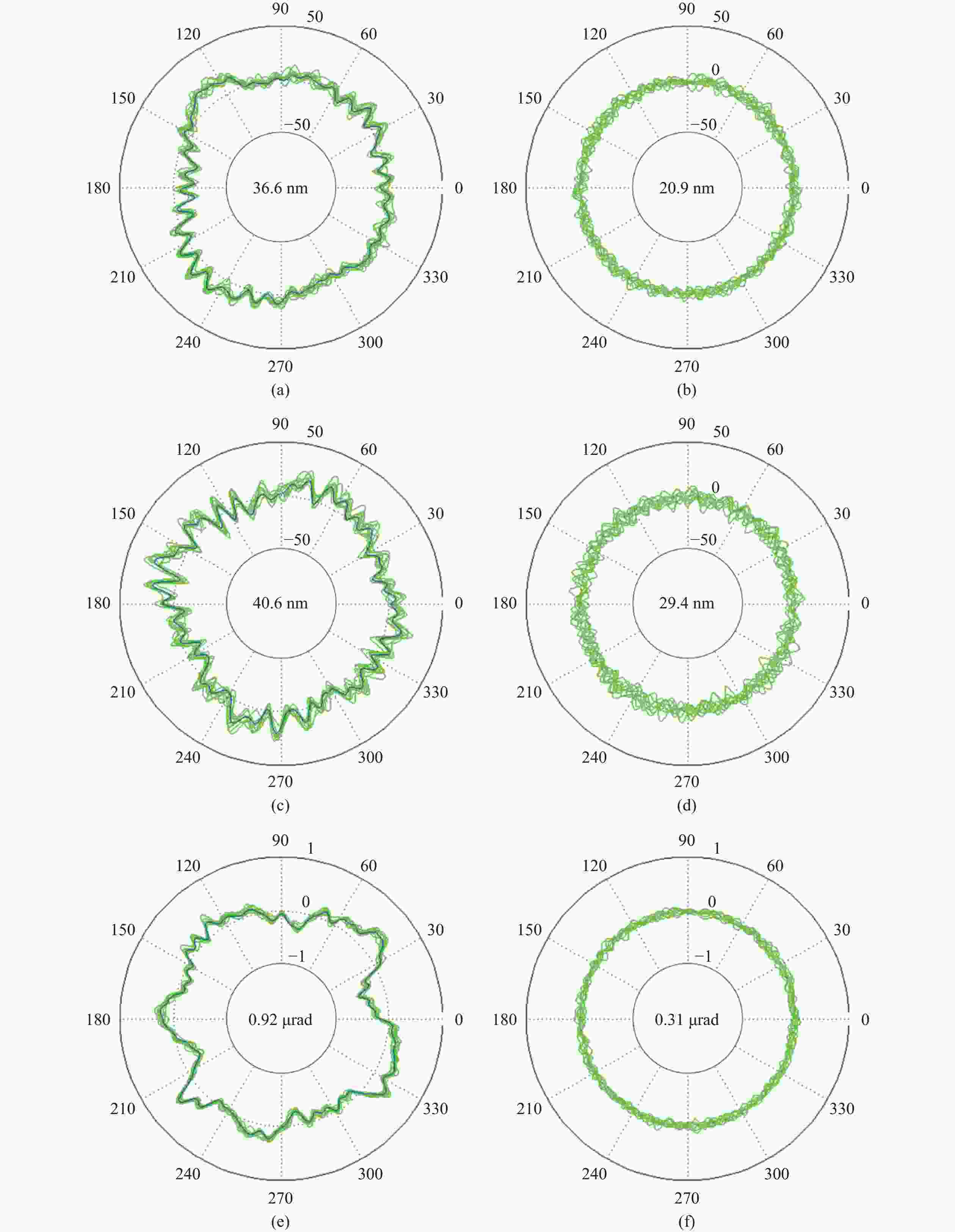
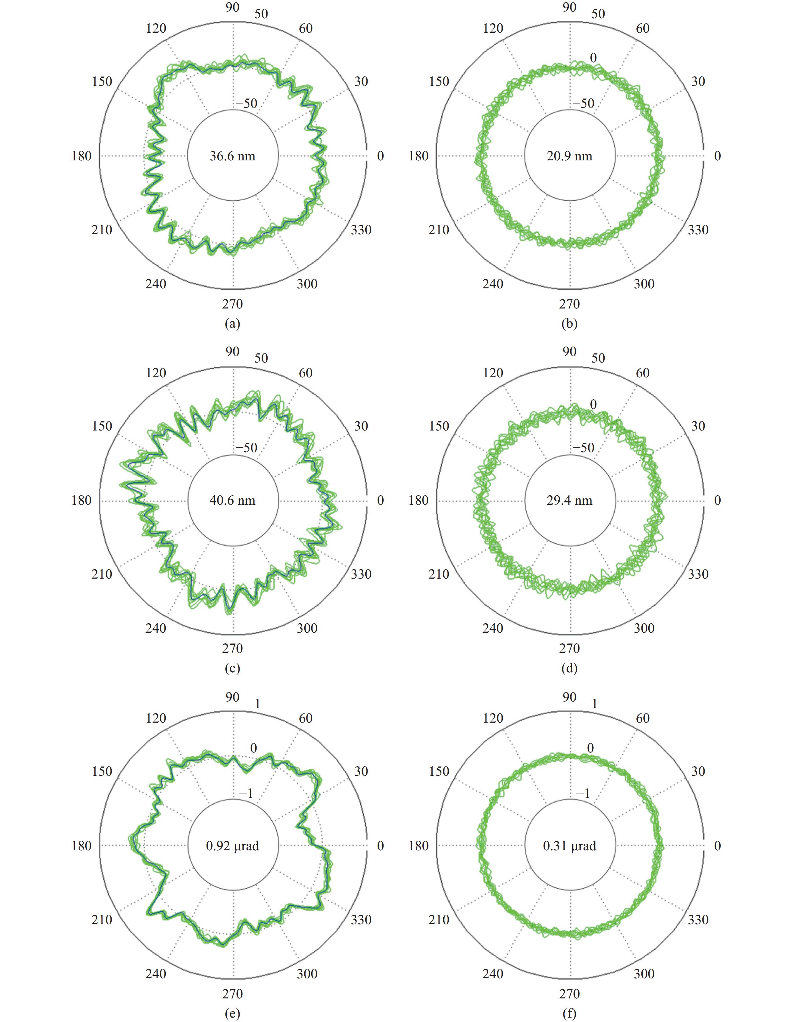
图 18 空气转轴的径向、轴向和角度误差信号(a 同步径向误差;b 异步径向误差;c 同步轴向误差;d 异步轴向误差;e 同步角度误差;f 异步角度误差)
Figure 18. Radial, axial and tilt error signals of the air spindle (a Synchronous radial error; b Asynchronous radial error; c Synchronous axial error; d Asynchronous axial error; e Synchronous tilt error; f Asynchronous tilt error)
表 1 回转运动误差在不同方向上的投影系数
Table 1. Projection coefficients of rotary axes error in different directions
回转轴
Spindle误差
Errort方向
t-directionx方向
x-directionn方向
n-direction样品
回转轴
Sample (S)σS,x 0 1 0 σS,y cos(δa) 0 sin(δa) σS,z sin(δa) 0 cos(δa) σS,a δz cos(δa) +
δy sin(δa)0 δz sin(δa) +
δy cos(δa)σS,b 0 δz 0 σS,c 0 δy 0 测头
回转轴
Probe (P)σP,x 0 1 0 σP,y cos(δa) 0 sin(δa) σP,z sin(δa) 0 cos(δa) σP,a Lp 0 0 σP,b 0 Lp cos(δa) 0 σP,c 0 Lp sin(δa) 0  下载: 导出CSV
-
[1] Z Jia, J Ma, D Song, et al. A review of contouring-error reduction method in multi-axis CNC machining[J]. Int. J. Mach. Tools Manuf, 2018, 125: 34-54. doi: 10.1016/j.ijmachtools.2017.10.008 [2] S Sepahi-Boroujeni, J Mayer, F Khameneifar. Repeatability of on-machine probing by a five-axis machine tool[J]. Int. J. Mach. Tools Manuf, 2020, 152: 103544. doi: 10.1016/j.ijmachtools.2020.103544 [3] F Fang, X Zhang, X Hu. Cylindrical coordinate machining of optical freeform surfaces[J]. Opt. Express, 2008, 16: 7323-7329. doi: 10.1364/OE.16.007323 [4] 位恒政, 王为农, 裴丽梅, 等. 面向任务的坐标测量机测量不确定度评价方法[J]. 计量科学与技术, 2021, 65(5): 115-119. doi: 10.12338/j.issn.2096-9015.2020.9053 [5] S Wang, C Cheung, M Ren, et al. Fiducial-aided on-machine positioning method for precision manufacturing of optical freeform surfaces[J]. Opt. Express, 2018, 26: 18928-18943. doi: 10.1364/OE.26.018928 [6] Z Sun, S To, K Yu. One-step generation of hybrid micro-optics with high-frequency diffractive structures on infrared materials by ultra-precision side milling[J]. Opt. Express, 2018, 26: 28161-28177. doi: 10.1364/OE.26.028161 [7] 熊俊, 熊乙锟, 陈龙, 等. 三坐标测量机校准结果影响因素分析[J]. 计量科学与技术, 2020(9): 54-57. doi: 10.3969/j.issn.1000-0771.2020.03.15 [8] K You, G Yan, F Fang, et al. Tool path generation of turning optical freeform surfaces using arbitrary rake angle tools[J]. Opt. Express, 2020, 28: 38252-38266. doi: 10.1364/OE.413113 [9] 赵红. 激光校准仪测量双主轴镗铣机床同轴度误差分析[J]. 计量科学与技术, 2022, 66(7): 65-69. [10] 叶晓明, 丁士俊, 师会生. 测量误差理论的真值中心论和测得值中心论[J]. 计量科学与技术, 2021, 65(3): 19-27. [11] Y Huang, K Fan, Z Lou, et al. A novel modeling of volumetric errors of three-axis machine tools based on Abbe and Bryan principles[J]. Int. J. Mach. Tools Manuf, 2020, 151: 103527. doi: 10.1016/j.ijmachtools.2020.103527 [12] Z Wang, D Wang, Y Wu, et al. An invariant approach replacing Abbe principle for motion accuracy test and motion error identification of linear axes[J]. Int. J. Mach. Tools Manuf, 2021, 166: 103746. doi: 10.1016/j.ijmachtools.2021.103746 [13] 靳浩元, 刘军. 测量不确定度的评定方法及应用研究[J]. 计量科学与技术, 2021, 65(5): 124-131. doi: 10.12338/j.issn.2096-9015.2020.9002 [14] Y Qiao, Y Chen, J Yang, et al. A five-axis geometric errors calibration model based on the common perpendicular line (CPL) transformation using the product of exponentials (POE) formula[J]. Int. J. Mach. Tools Manuf, 2017, 118: 49-60. [15] S Zhu, G Ding, S Qin, et al. Integrated geometric error modeling, identification and compensation of CNC machine tools[J]. Int. J. Mach. Tools Manuf, 2011, 52: 23-29. [16] S Ibaraki, R Okumura. A machining test to evaluate thermal influence on the kinematics of a five-axis machine tool[J]. Int. J. Mach. Tools Manuf, 2021, 163: 103702. doi: 10.1016/j.ijmachtools.2021.103702 [17] Z Wang, D Wang, S Yu, et al. A reconfigurable mechanism model for error identification in the double ball bar tests of machine tools[J]. Int. J. Mach. Tools Manuf, 2021, 163: 103737. [18] K Hii, R Vallance, R Grejda, et al. Error motion of a kinematic spindle[J]. Precis. Eng, 2004, 28: 204-217. doi: 10.1016/j.precisioneng.2003.11.001 [19] R Henselmans, L Cacace, G Kramer, et al. The Nanomefos non-contact measurement machine for freeform optics[J]. Precis. Eng, 2011, 35: 607-624. doi: 10.1016/j.precisioneng.2011.04.004 [20] J Petter, G Berger. Non-contact profiling for high precision fast asphere topology measurement[J]. Proc. SPIE, 2013, 81: 878819. [21] D Martin, A Tabenkin, F Parsons. Precision spindle and bearing error analysis[J]. Int. J. Mach. Tools Manuf, 1995, 35: 187-193. doi: 10.1016/0890-6955(94)P2372-M [22] R Grejda, E Marsh, R Vallance. Techniques for calibrating spindles with nanometer error motion[J]. Precis. Eng, 2005, 29: 113-123. doi: 10.1016/j.precisioneng.2004.05.003 [23] S Cappa, D Reynaerts, F Al-Bender. A sub-nanometre spindle error motion separation technique[J]. Precis. Eng, 2014, 38: 458-471. doi: 10.1016/j.precisioneng.2013.12.011 [24] E Marsh, J Couey, R Valance. Nanometer-level comparison of three spindle error motion separation techniques[J]. Journal of Manufacturing Science and Engineering, 2006, 128(1): 180-187. doi: 10.1115/1.2118747 [25] H Castro. A method for evaluating spindle rotation errors of machine tools using a laser interferometer[J]. Measurement, 2008, 41: 526-537. doi: 10.1016/j.measurement.2007.06.002 [26] K Anandan, O Ozdoganlar. An LDV-based methodology for measuring axial and radial error motions when using miniature ultra-high-speed (UHS) micromachining spindles[J]. Precis. Eng, 2013, 37: 172-186. doi: 10.1016/j.precisioneng.2012.08.001 [27] K Anandan, O Ozdoganlar. Analysis of error motions of ultra-high-speed (UHS) micromachining spindles[J]. Int. J. Mach. Tools Manuf, 2013, 70: 1-14. doi: 10.1016/j.ijmachtools.2013.02.005 [28] B Bediz, B Gozen, E Korkmaz, et al. Dynamics of ultra-high-speed (UHS) spindles used for micromachining[J]. Int. J. Mach. Tools Manuf, 2014, 87: 27-38. doi: 10.1016/j.ijmachtools.2014.07.007 [29] A Jin, J Chen, W Yang, et al. Measurement of spindle radial error based on target trajectory tracking[J]. Measurement, 2019, 146: 179-185. doi: 10.1016/j.measurement.2019.05.026 [30] W Jywe, C Chen. The development of a high-speed spindle measurement system using a laser diode and a quadrants sensor[J]. Int. J. Mach. Tools Manuf, 2005, 45: 1162-1170. doi: 10.1016/j.ijmachtools.2004.12.002 [31] C Liu, W Jywe, H Lee. Development of a simple test device for spindle error measurement using a position sensitive detector[J]. Meas. Sci. Technol, 2004, 15: 1733-1741. doi: 10.1088/0957-0233/15/9/009 [32] K Fujimaki, K Mitsui. Radial error measuring device based on auto-collimation for miniature ultra-high-speed spindles[J]. Int. J. Mach. Tools Manuf, 2007, 47: 1677-1685. doi: 10.1016/j.ijmachtools.2007.01.002 [33] H Murakami, A Katsuki, T Sajima. Simple and simultaneous measurement of five-degrees-of-freedom error motions of high-speed microspindle: Error analysis[J]. Precis. Eng, 2014, 38: 249-256. doi: 10.1016/j.precisioneng.2013.09.005 [34] H Murakami, N Kawagoishi, E Kondo, et al. Optical technique to measure five-degree-of-freedom error motions for a high-speed microspindle[J]. Int. J. Precis. Eng. Manuf, 2010, 11: 845-850. doi: 10.1007/s12541-010-0102-4 [35] W Zhao, J Tan, L Qiu. Bipolar absolute differential confocal approach to higher spatial resolution[J]. Opt. Express, 2004, 12: 5013-5021. doi: 10.1364/OPEX.12.005013 [36] L Zou, J Qu, S Hou, et al. Differential confocal technology based on radial birefringent pupil filtering principle[J]. Opt. Commun, 2012, 285: 2022-2027. doi: 10.1016/j.optcom.2011.12.062 [37] L Zou, Y Chen, J Qu, et al. Response characteristics of differential confocal system based on radial birefringent pupil[J]. Opt. Commun, 2013, 303: 15-20. doi: 10.1016/j.optcom.2013.04.006 [38] D Rector, D Ranken, J George. High-performance confocal system for microscopic or endoscopic applications[J]. Methods, 2003, 30: 16-27. doi: 10.1016/S1046-2023(03)00004-5 [39] L Li, C Kuang, Y Xue, et al. Nano-displacement measurement based on virtual pinhole confocal method[J]. Meas. Sci. Technol, 2013, 24: 03500. [40] H Ni, W Zhao, L Qiu. Measurement method of spindle motion error based on composite laser target[J]. Int. J. Mach. Tools Manuf, 2022, 174: 103860. doi: 10.1016/j.ijmachtools.2022.103860 -


 点击查看大图
计量
- 文章访问数: 154
- HTML全文浏览量: 72
- PDF下载量: 18
- 被引次数: 0

